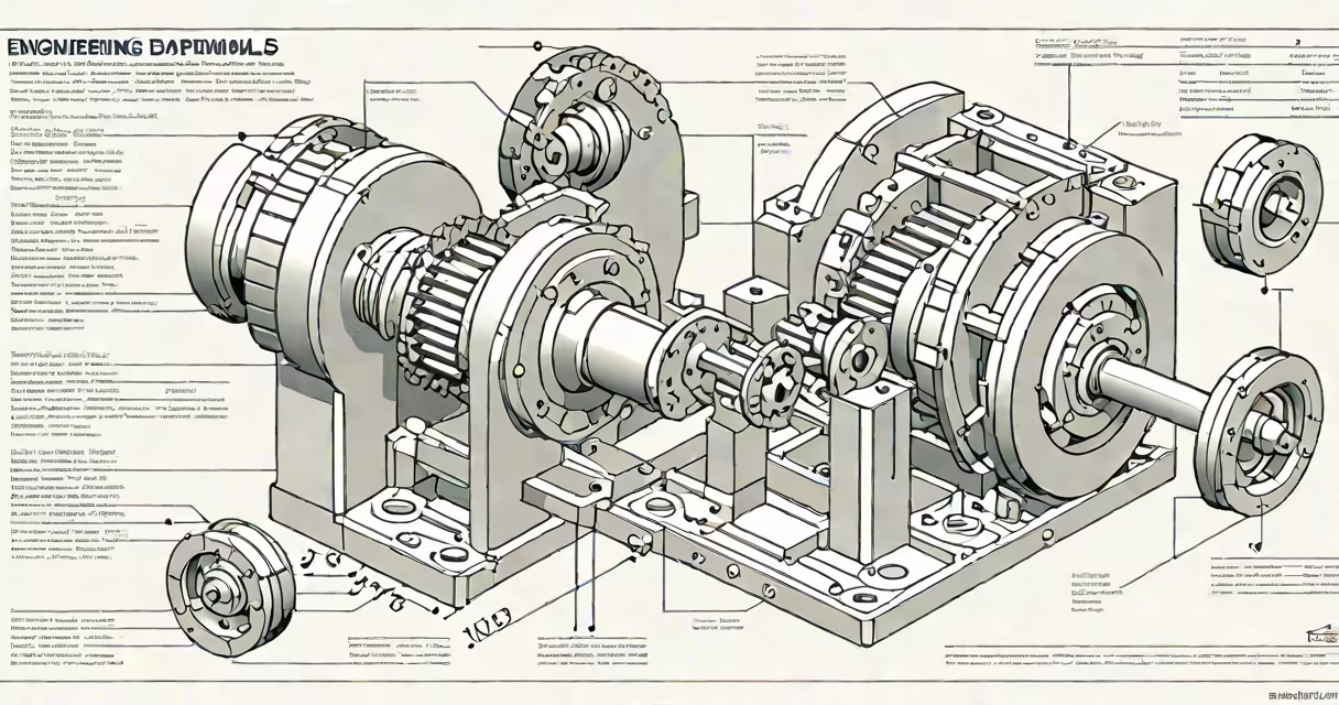
Engineering drawing fundamentals are standardized visual representations used to communicate precise geometric, dimensional, and material specifications for manufactured parts and assemblies. These drawings serve as the primary language between engineers, designers, and manufacturers, ensuring consistency and accuracy across production.
Every engineering drawing follows established conventions governed by organizations such as the American Society of Mechanical Engineers (ASME) and the International Organization for Standardization (ISO). These standards define how views are arranged, how dimensions are annotated, and how tolerances are applied. Without adherence to these rules, even minor misinterpretations can lead to costly manufacturing errors or safety failures.
For example, a single shaft with a 15 mm diameter and a 2 mm chamfer must be drawn using orthographic projection with front, top, and side views. The chamfer must be specified using a 45° angle and a dimension of 0.5 mm, not just a sketch. This precision helps the machinist produces the correct feature regardless of location or experience level.
Drawings convey three-dimensional objects on a two-dimensional surface using multiple orthogonal views. The most common setup includes front, top, and right-side projections aligned according to first-angle or third-angle projection systems. Third-angle projection is standard in the United States; first-angle is used in Europe and Asia.
Each view shows only the features visible from that direction. Hidden lines (dashed) represent internal features not visible in the current view. Visible edges are solid lines. Centerlines (alternating long-short dashes) indicate symmetry axes or centers of holes and arcs.
Dimensioning is critical. Dimensions must be unambiguous and complete. For instance, a hole's diameter must be stated explicitly-"⌀10 mm"-not implied. ASME Y14.5 specifies that dimensions should be placed on the view where the feature is most shown, avoiding duplication and redundancy.
Key components of an engineering drawing include:
Standard drawing formats follow ISO 216 or ANSI Y14.1. Common sizes include A4 (210 × 297 mm), A3 (297 × 420 mm), and A2 (420 × 594 mm). Title blocks contain essential metadata: part name, material, scale, revision number, and approval signatures.
| Type | Use Case | Example |
|---|---|---|
| Orthographic | General part layout | Front, top, and side views of a bracket |
| Sectional | Internal features | Cross-section of a gear housing |
| Isometric | Concept visualization | 3D-style view for design review |
| Detail | Small feature enlargement | 放大 5x of a threaded hole |
One common mistake is assuming isometric drawings are sufficient for manufacturing. They're useful for communication but lack precise dimensions and tolerances. A part drawn only in isometric form cannot be produced reliably.
Engineering drawings prevent errors during fabrication. A study by the National Institute of Standards and Technology (NIST) found that poor documentation costs U.S. manufacturers $1.5 billion annually in rework and delays. Clear, accurate drawings reduce ambiguity and improve quality control.
In aerospace, automotive, and medical device industries, compliance with ASME Y14.5 and ISO 129 is mandatory. For example, a prosthetic implant must be dimensioned within ±0.05 mm tolerance. Any deviation risks patient injury or regulatory rejection.
When I designed a custom gearbox for a robotics team, we used a combination of orthographic and section views. We included GD&T (Geometric Dimensioning and Tolerancing) symbols to specify concentricity and flatness. The manufacturer initially missed a key tolerance, leading to gear misalignment. After adding a formal callout with a feature control frame, the part passed inspection on the first try.
Many assume that engineering drawings are artistic renderings. They are not. A drawing is a functional document-not a sketch. Lines are not freehand; they are drawn with tools or CAD software to exact scale. Dashed lines are not suggestions-they represent hidden geometry.
Another misconception is that "scale" means the drawing is smaller than the actual part. Scale is a ratio: 1:1 means full size, 2:1 means double size, 1:2 means half size. A drawing at 1:1 scale of a 100 mm part must show exactly 100 mm, regardless of paper size.
GD&T is frequently misunderstood. It's not optional-it's a system for defining allowable variation in form, orientation, and position. For example, a hole's position must lie within a cylindrical zone of 0.1 mm diameter, controlled by a positional tolerance symbol. This ensures mating parts fit correctly even if individual dimensions vary slightly.
ASME Y14.5-2018 states that "dimensions shall be applied to features of interest, not to reference points." Many beginners place dimensions from a corner that isn't a feature, leading to confusion. Always dimension from actual surfaces or centerlines.
Understanding engineering drawing fundamentals is important for passing the mechanical fundamentals of engineering exam. The exam tests your ability to read and interpret drawings, apply tolerances, and understand projection methods.
Practice interpreting multi-view drawings with hidden lines and section cuts. Focus on identifying the correct projection method-third-angle vs. first-angle-and recognizing how features are projected across views. Learn to read feature control frames and identify geometric tolerances like perpendicularity, concentricity, and runout.
Engineers who master these fundamentals avoid costly redesigns, reduce prototyping cycles, and ensure product reliability. a satellite component, clear, accurate drawings are non-negotiable.