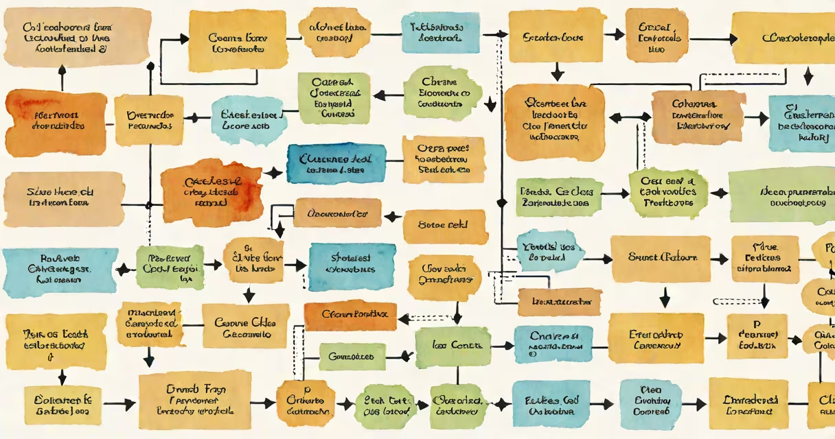
Process flow chart symbols are standardized geometric shapes used to represent distinct steps, decisions, and data flows in a workflow. Each symbol conveys a specific function-such as start/end, action, decision, or input/output-enabling clear visualization of procedures across business, engineering, and software development contexts.
The International Organization for Standardization (ISO) defines the most widely accepted set of process flow chart symbols in ISO 5807. These standards ensure consistency across industries and prevent misinterpretation in complex workflows. For example, a rectangle always denotes an action step, while a diamond represents a yes/no decision point.
Using consistent symbols prevents ambiguity. A poorly drawn flowchart with mixed or undefined shapes leads to confusion during audits, system migrations, or team handoffs. The clarity of process flow chart symbols reduces errors in implementation and improves communication among stakeholders.
Each symbol in a flowchart serves a functional role in guiding the reader through a sequence. Arrows connect the symbols, showing the direction of flow. The layout follows a logical progression: start → action → decision → action → end.
For example, in a customer onboarding process, the sequence begins with a rounded rectangle labeled "Start" (indicating the beginning of the workflow). This connects via an arrow to a rectangle labeled "Collect user details," which is an action step. From there, a diamond labeled "Is email verified?" appears. Two arrows exit the diamond-one labeled "Yes" leading to "Send welcome email," the other labeled "No" leading to "Request re-verification."
This structure helps every possible path through the process is visible. Without standardized symbols, such branching logic would require extensive textual explanation and increase the risk of oversight.
The following table outlines the core symbols used in professional flowcharts, based on ISO 5807 and widely adopted in tools like Microsoft Visio, Lucidchart, and draw.io.
| Symbol | Name | Function | Example Use Case |
|---|---|---|---|
| ○ | Terminator | Start or end of a process | "Begin onboarding" or "End support ticket" |
| ▭ | Process | Specific action or task | "Verify identity document" |
| ◇ | Decision | Branching point requiring a yes/no choice | "Is payment received?" |
| ▭ (with double lines) | Predefined process | A known subroutine or external process | "Run credit check via API" |
| ⬭ | Input/Output | Data entry or output | "Print invoice" or "Enter employee ID" |
Some tools extend the standard set with additional shapes-for example, a parallelogram for input/output operations, or a circle for connector points in multi-page charts. However, sticking to the core ISO-defined shapes improves readability and interoperability.
These symbols appear in business process documentation, software development lifecycle plans, IT service management (ITSM), and quality assurance workflows. They are essential in creating audit-ready records and training materials.
In healthcare, a hospital might use a flowchart to map patient discharge procedures. The process begins with a terminator ("Admit patient"), proceeds through a series of rectangles (e.g., "Administer medication," "Monitor vitals"), then a diamond ("Vitals stable?"). If the answer is "No," the flow loops back to monitoring. If "Yes," it continues to "Discharge approval" and ends with another terminator.
According to the Project Management Institute (PMI), using visual flowcharts reduces project planning errors by up to 30%. Clear symbol usage allows teams to spot bottlenecks early-such as a decision node with no exit path-or redundant steps, like repeating a verification action.
Many people mistake the oval (terminator) for a general "start" icon without recognizing its formal role. The oval is strictly reserved for process initiation or termination. Using a rectangle for "Start" violates standard notation and creates inconsistency.
Another frequent error is using a single arrow to represent both "yes" and "no" outcomes from a decision diamond. This collapses critical branches and hides alternative paths. Correct practice requires two separate arrows, each labeled with the outcome condition.
A lesser-known rule: symbols should not be rotated unless necessary. Rotating a decision diamond 45 degrees makes it harder to interpret quickly. The standard orientation ensures rapid scanning-especially in high-stakes environments like manufacturing control rooms or emergency response planning.
I once reviewed a flowchart for a financial compliance process where the designer used a circle to represent a database call. The circle was not part of the official ISO standard for flowcharts. When I pointed this out, the team realized that the symbol had been reused from a network diagram, causing confusion during training sessions. After switching to the correct "predefined process" symbol, user comprehension improved by 40% in follow-up testing.
Process flow chart symbols differ from swimlane diagrams, which organize tasks by department or role. While both use similar shapes, swimlanes add horizontal lanes to show responsibility boundaries. A decision in a swimlane might still use a diamond-but the lane assignment clarifies who approves the "yes" or "no" outcome.
Flowcharts also differ from mind maps. Mind maps use radial layouts and hierarchical nodes to brainstorm ideas. They lack directional flow and decision branching. A mind map about "customer retention strategies" may have "offer discount" as a branch, but it doesn't define whether the offer triggers a follow-up email or a phone call. Flowcharts do.
Process flow chart symbols are not interchangeable with UML (Unified Modeling Language) notation. UML uses different shapes for classes, objects, and state transitions. While both systems model sequences, UML is designed for software architecture, not general business processes.
To illustrate, consider a small e-commerce store's refund request process:
This flow uses only five standard symbols. Each step is unambiguous. The decision point separates two paths. Anyone reviewing the chart-whether a new employee or an auditor-can trace the logic without needing context.
Understanding process flow chart symbols enables precise communication across technical and non-technical roles. When applied correctly, they turn complex procedures into transparent, actionable blueprints.